Electrical Mapping in the Virtual Cell allows the user to model cell electrophysiology. Electrical Mapping specifies the Membrane Potential Options and Electrical Stimulus that can be applied to flux reactions. Electrical Mapping is available in both spatial and compartmental models. In compartmental models one cannot specify electrode clamp.

Viewing/Editing Electrical Mapping
Electrical mapping can be accessed by choosing the 'Protocols' item in any application in the 'Navigation' panel tree structure. This opens the 'Protocols' tab in the 'View' panel on the right. In this tab, choosing the Electrical tab allows the user to view/edit electrical mapping parameters for the application.
The Membrane Potential Options table lists the membranes in the BioModel. The user has the option of specifying the initial voltage (V initial) and the Specific Capacitance of each membrane. By default the checkbox for calculating the voltage is checked. The user can choose between four options from the drop-down menu for electrical Stimulus: no clamp, voltage clamp total current clamp or current density clamp. If the user wishes to switch from the voltage/current clamp to any other clamp options, a warning message will be displayed indicating that the present clamp settings will be lost.

When 'Voltage' or 'Current' clamps (stimuli) is chosen, the required attributes that can be specified are displayed in a table. The available electrical stimulus options are:
No Clamp
There is no stimulus applied across the membrane, so no clamp device is displayed. The 'Patch Electrode', 'Ground Electrode', 'Preview Electrical Stimulus' button are disabled for this option.
Voltage Clamp
A voltage clamp or stimulus is applied across the membrane. When the 'Voltage Clamp' radio button is selected, the required attributes for the voltage clamp device, i.e., the features of the probe (patch) and ground electrodes, and the voltage expression (in 'milliVolts') can be specified.
Total Current Clamp
A current clamp or stimulus is applied across the membrane. When the 'Current Clamp' radio button is selected, the required attributes for the current clamp device, i.e., the features of the probe (patch) and ground electrodes, and the current expression (in 'picoAmperes') can be specified.
Current Density Clamp
A current density clamp or stimulus is applied across membrane. When the 'Current Density Clamp' radio button is selected, the required attributes for the current clamp device, i.e., the features of the probe (patch) and ground electrodes, and the current expression (in picoAmperes-2) can be specified.
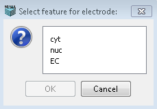
The Patch Electrode and Ground Electrode can be specified for the different applied electrical stimulus options. These are features (volumetric compartments) present in the model. Clicking the Set button pops up a dialog that lists the features in the model. Choosing a feature from the list and clicking OK will set the electrode (Patch or Ground) to that feature.

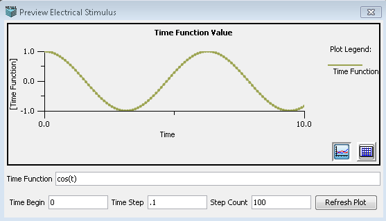
The Preview Electrical Stimulus button can be used to preview the chosen electrical stimulus. It displays the stimulus as a time plot. The user can change the Time Function, Time Begin, Time Step and Step Count in the text fields provided. Clicking Refresh Plot button will refresh the display to reflect the modified 'Time Function'.
